


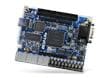
Terasic Technologies MAX 10 Plus Board
Terasic Technologies MAX 10 Plus Board offers a full featured embedded evaluation platform based upon the MAX10 family of Intel® field-programmable gate arrays (FPGAs). Terasic Technologies MAX 10 Plus board offers a comprehensive design environment with everything embedded to create a processing-based system. Hardware, design tools, intellectual property, and reference designs are all included, enabling the development of a wide range of audio, video, and IoT applications.
Features
- 233.35mm x 160mm dimensions
- FPGA device
- MAX 10 10M50DAF484C6G device
- Integrated dual ADCs, each ADC supports 1 dedicated analog input and 8 dual function pins
- 50K programmable logic elements
- 1638Kbit M9K memory
- 5888Kbits user flash memory
- 144 18 x 18 Multiplier
- 4 PLLs
- Configuration and debug
- Onboard USB-Blaster II (Mini USB type B connector)
- Optional JTAG direct via 10-pin header
- Slide switch for dual boot image selection
- Memory devices
- 64M x16 1Gb DDR3 SDRAM
- 128M x8 1Gb DDR3 SDRAM
- 512Mb quad serial peripheral interface (quad SPI) flash memory
- Micro SD card socket
- Communication and expansion
- Gigabit Ethernet PHY with RJ45 connector
- UART to USB
- PS/2 mouse/keyboard connector
- 2x6 TMD expansion header
- Audio/video
- 24-bit CD-quality audio CODEC with mic-in, line-in, line-out jacks
- HDMI video input
- Analog
- 2x MAX 10 FPGA ADC SMA inputs
- Potentiometer input to ADC
- Onboard MIC input to ADC
- 2x10 header for MAX 10 FPGA
- ADC inputs
- 1x DAC output
- Sensors
-
Humidity and temperature sensor
-
Light sensor
-
Accelerometer
-
Power monitor
-
- Clocking for users
- 1x 10MHz single-ended, external oscillator clock source
- 3x 50MHz single-ended, external oscillator clock source
- Switches, buttons, and LEDs
- 5x pushbuttons
- 10x slide switches
- 10x red user LEDs
- 2x 7-segment displays
- 5V/3A DC input power
Kit Contents

Board Layout

Block Diagram

Applicable Products

Altera MAX® 10 FPGAs
Single-chip solution that integrates advanced processing, non-volatile flash memory, RAM, and ADCs.

Altera Quartus® Prime Design Software
Multi-platform design environment for all phases of FPGA and CPLD design.
Related Products
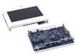
Terasic Technologies MAX 10 NEEK Evaluation Kit
A comprehensive design environment for Altera Max10 FPGAs with included LCD touch panel.
Terasic Technologies DE10-Lite Board
A robust hardware design platform built around the Altera MAX 10 Field-Programmable Gate Array.
Opublikowano: 2019-07-11
| Zaktualizowano: 2024-02-26