


Microchip Technology PIC16F18013/14/23/24 Full-Featured 8/14-Pin MCUs
Microchip Technology PIC16F18013/14/23/24 Full-Featured 8/14-Pin Microcontrollers (MCUs) feature a suite of digital and analog peripherals that enable cost-sensitive sensor and real-time control applications. This product family is available from 8-pin to 44-pin packages in a memory range of 3.5KB to 28KB, with speeds up to 32MHz. The PIC16F18013/14/23/24 MCUs include a 10-bit Analog-to-Digital Converter with Computation (ADCC), automated Capacitive Voltage Divider (CVD) techniques for advanced capacitive touch sensing, an 8-bit Digital-to-Analog Converter (DAC) module, and many more waveform control and communication peripherals. These small form factor, feature-rich devices are well suited for low-cost sensor and control applications.
Features
- Core
- C compiler-optimized RISC architecture
- Operating speed
- DC to 32MHz clock input
- 125ns minimum instruction time
- 16-level deep hardware stack
- Low-current power-on reset (POR)
- Configurable power-up timer (PWRT)
- Brown-out reset (BOR)
- Watchdog timer (WDT)
- Memory
- Up to 28KB of program flash memory
- Up to 2KB of data SRAM memory
- Up to 256-bytes of data EEPROM memory
- Memory access partition (MAP) with program flash memory partitioned into:
- Application block
- Boot block
- Storage area flash (SAF) block
- Programmable code and write protection
- Device information area (DIA) stores
- Fixed voltage reference (FVR) measurement data
- Microchip unique identifier (MUI)
- Device characteristics information (DCI) stores
- Program/erase row sizes
- Pin count details
- Direct, indirect, and relative addressing modes
- 1.8V to 5.5V operating voltage range
- Operating temperature ranges
- -40°C to +85°C industrial
- -40°C to +125°C extended
- Power-saving functionality
- Sleep
- Reduce device power consumption
- Reduce system electrical noise while performing ADC conversions
- Low power mode
- <900nA typical sleep at 3V/25°C (WDT enabled)
- <600nA typical sleep at 3V/25°C (WDT disabled)
- 48µA typical operating current at 32kHz, 3V/25°C
- <1mA typical operating current at 4MHz, 5V/25°C
- Sleep
- Analog peripherals
- Analog-to-digital converter with computation (ADCC)
- 10-bit resolution
- Up to 35x external input channels
- 4x internal input channels
- Internal ADC oscillator (ADCRC)
- Operates in sleep
- Selectable auto-conversion trigger sources
- Charge pump module improves accuracy of analog modules at low voltages
- 8-bit digital-to-analog converter (DAC)
- Output available on 1x I/O pin
- Internal connections to ADC and comparators
- 1x comparator (CMP)
- Up to 4x external inputs
- Configurable output polarity
- External output via peripheral pin select
- Zero-cross detect (ZCD) detects when the AC signal on the pin crosses the ground
- 2x fixed voltage references (FVR)
- Selectable 1.024V, 2.048V, and 4.096V output levels
- FVR1 internally connected to ADC
- FVR2 internally connected to the comparator and DAC
- Analog-to-digital converter with computation (ADCC)
- Digital peripherals
- 2x capture/compare/PWM (CCP) modules
- 16-bit resolution for capture/compare modes
- 10-bit resolution for pulse-width modulator (PWM) mode
- 3x pulse-width modulators (PWM) with a 10-bit resolution
- 4x configurable logic cells (CLC) with integrated combinational and sequential logic
- 1x configurable 8/16-bit timer (TMR0)
- 2x 16-bit timers (TMR1/3) with gate control
- 3x 8-bit timers (TMR2/4/6) with hardware limit timer (HLT)
- 1x numerically controlled oscillator (NCO)
- Generates true linear frequency control and increased frequency resolution
- Input clock up to 64MHz
- Up to 2x enhanced universal synchronous asynchronous receiver transmitters (EUSART)
- RS-232, RS-485, and LIN compatible
- Auto wake-up on start
- Up to 2x host synchronous serial ports (MSSP)
- Serial peripheral interface (SPI) mode with client-select synchronization
- Inter-integrated circuit (I2C) mode with 7/10-bit addressing modes
- Peripheral pin select (PPS) enables pin mapping of digital I/O
- Device I/O port
- Up to 35x I/O pins
- 1x input-only pin
- Individual I/O direction, open drain, input threshold, slew rate, and weak pull-up control
- Interrupt-on-change (IOC) on up to 25x pins
- 1x external interrupt pin
- 2x capture/compare/PWM (CCP) modules
- Clocking structure
- High-precision internal oscillator block (HFINTOSC)
- Selectable frequencies up to 32MHz
- ±2% at calibration
- Internal 31kHz oscillator (LFINTOSC)
- External high-frequency clock input with 2x external clock (EC) power modes
- Secondary Oscillator (SOSC)
- High-precision internal oscillator block (HFINTOSC)
- Programming/debug
- In-circuit serial programming™ (ICSP™) via 2x pins
- In-circuit debug (ICD) with 3x breakpoints via 2x pins
- Debug integrated on-chip
- 8-pin PDIP, 8-pin SOIC, 8-pin DFN, 14-pin PDIP, 14-pin SOIC, 14-pin TSSOP, and 16-pin QFN package options
Applications
- Cost-sensitive sensor applications
- Real-time control applications
Block Diagram

Core Data Path Diagram

Related Products
Microchip Technology PIC16F18054/55/74/75 Microcontrollers
Feature 128 bytes data flash memory (EEPROM) and 7KB/14KB program flash memory.

Microchip Technology Mikrokontrolery 8-bitowe PIC16F18056 i PIC16F18076
Urządzenia mieszczące się w kompaktowych obudowach, wyposażone w różnorodne funkcje, idealne do niskobudżetowych zastosowań wymagających czujników i elementów sterowania.
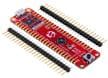
Microchip Technology EV53Z50A PIC16F18076 Curiosity Nano Evaluation Kit
Features full programming and debugging capabilities for the PIC16F18076.
Microchip Technology 8-Bit PIC® & AVR® Microcontrollers
Versatile microcontroller families with an extensive portfolio of development and support tools.
Opublikowano: 2024-05-06
| Zaktualizowano: 2024-10-14